Full Details on Instruction Cycle or Fetch-Decode-Execute
Instruction Cycle — বাংলা ও English আলাদা সংস্করণ
চিত্র সম্পর্কে নোট / Image note: Original article-এর ২৫টি educational image বাংলা অংশে এবং একই ২৫টি image English অংশে lesson-এর সঠিক জায়গায় বসানো হয়েছে। কোনো image recreate বা replace করা হয়নি। শুধু ৬টি course/advertisement image বাদ দেওয়া হয়েছে।
এই নথিতে দুই ভাষা সম্পূর্ণ আলাদা অংশে সাজানো হয়েছে। প্রথমে সম্পূর্ণ বাংলা সংস্করণ, তারপর সম্পূর্ণ English version দেওয়া হয়েছে।
ইনস্ট্রাকশন সাইকেল: সম্পূর্ণ বাংলা সংস্করণ
কম্পিউটার অর্গানাইজেশন ও আর্কিটেকচার
নোট: এই অংশে বাংলা ব্যাখ্যা সম্পূর্ণ আলাদাভাবে দেওয়া হয়েছে। CPU, ISA, Fetch, Decode, Execute, Opcode, Operand এবং RTL-এর মতো প্রয়োজনীয় technical term ইংরেজিতেই রাখা হয়েছে, যাতে বিষয়ভিত্তিক অর্থ ঠিক থাকে। মূল শিক্ষামূলক বিষয়, ধাপ, উদাহরণ, equation বা প্রয়োজনীয় diagram বাদ দেওয়া হয়নি।
সূচিপত্র
- Instruction Cycle কী?
- কম্পিউটার কীভাবে Program Execute করে?
- Computer Program কী?
- Program Instruction কী?
- Central Processing Unit (CPU) কী?
- CPU Instruction Set Architecture (ISA)
- Instruction Format কী?
- Opcode কী?
- Operand কী?
- Addressing Mode কী?
- Machine Cycle কী?
- Instruction Cycle ও Clock Pulse
- CPU Clock Speed ও Instruction Cycle
- Pipelined Architecture
- Non-Pipelined Architecture
- Fetch–Decode–Execute Cycle: ধাপে ধাপে
- Halt Phase ও Interrupt
Instruction Cycle হলো CPU-এর একটি instruction সম্পন্ন করতে প্রয়োজনীয় সময়। এটি CPU-এর একটি মৌলিক কাজ এবং সাধারণভাবে তিনটি প্রধান ধাপে বোঝানো হয়: Fetch, Decode এবং Execute।
একটি program-এর instruction সম্পন্ন করার জন্য CPU বারবার Fetch–Decode–Execute Cycle চালায়। Machine Cycle হলো Instruction Cycle-এর একটি অংশ।
কম্পিউটার সিস্টেমের প্রধান কাজ হলো program execute করা। একটি computer program অনেকগুলো instruction নিয়ে গঠিত। এসব instruction execute করার দায়িত্ব Central Processing Unit (CPU)-এর।
১. Instruction Cycle কী?
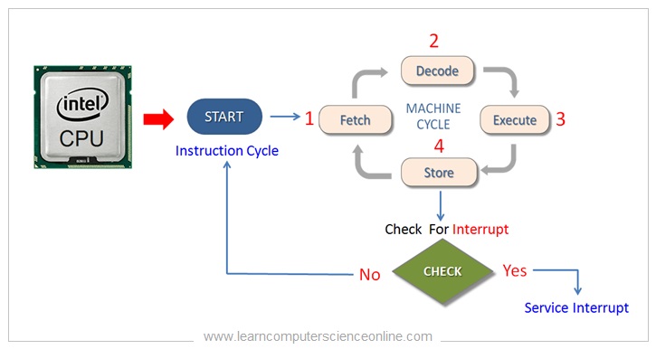
চিত্র ১: CPU Instruction Cycle-এর সামগ্রিক flow।
Program-এর instructionগুলো main memory বা RAM-এ সংরক্ষিত থাকে। Computer memory অনেকগুলো cell দিয়ে সাজানো থাকে। প্রতিটি cell বা location-এর একটি নির্দিষ্ট memory address থাকে।
Processor main memory থেকে machine instruction একটি একটি করে এনে program execution শুরু করে।
CPU বারবার নিচের চারটি কাজ করে instruction execute করে:
- Fetch — instruction নিয়ে আসা
- Decode — instruction-এর অর্থ বোঝা
- Execute — নির্ধারিত কাজ করা
- Store — ফলাফল সংরক্ষণ করা
Instruction Cycle-এর প্রতিটি অংশ সম্পন্ন করতে এক বা একাধিক Machine Cycle লাগতে পারে।
গুরুত্বপূর্ণ পরিষ্কার ধারণা: মূল লেখায় প্রথমে তিনটি বড় ধাপ—Fetch, Decode ও Execute—বলা হয়েছে। পরে Store-কে চতুর্থ operation হিসেবে দেখানো হয়েছে। দুটোই একই instruction execution process বোঝায়। তিন ধাপের ব্যাখ্যায় result store করাকে Execute ধাপের অংশ হিসেবে ধরা হয়।
২. কম্পিউটার কীভাবে Program Execute করে?
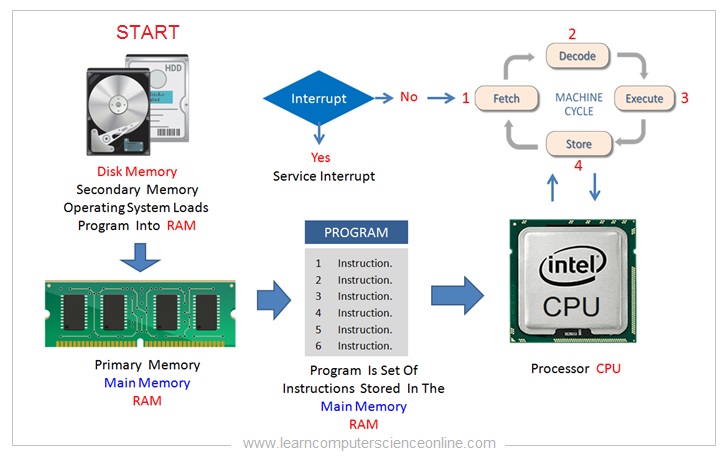
চিত্র ২: Program execution এবং Instruction Cycle-এর সম্পর্ক।
কম্পিউটার কীভাবে program execute করে তা বুঝতে নিচের সম্পর্কিত বিষয়গুলো আগে জানা দরকার:
- Computer Program
- Program Instruction
- Central Processing Unit বা CPU
- Instruction Set Architecture বা ISA
- Instruction Format
- Opcode ও Operand
- Addressing Mode
- Machine Cycle
- CPU Clock Speed
- Instruction Cycle
এই মৌলিক বিষয়গুলো থেকে বোঝা যায়, Control Unit কীভাবে instruction decode করে এবং CPU কীভাবে পুরো Instruction Cycle সম্পন্ন করে।
৩. Computer Program কী?
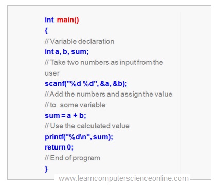
চিত্র ৩: Computer Program-এর মৌলিক ধারণা।
কম্পিউটারকে প্রয়োজনীয় কাজ করানোর জন্য কিছু instruction দিতে হয়। কম্পিউটার যে instructionগুলো বুঝতে এবং execute করতে পারে, সেই instruction-এর সমষ্টিকে Computer Program বলা হয়।
Computer Program প্রতিটি computer system-এর একটি প্রয়োজনীয় অংশ। কী ধরনের software তৈরি হবে, তার ওপর programming language নির্বাচন করা হয়।
Application software সাধারণত high-level programming language দিয়ে লেখা হয়। যেমন:
- C
- C++
- Java
- JavaScript
- Python
Program Compile করার প্রক্রিয়া
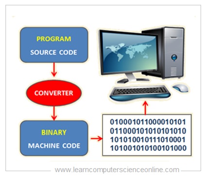
চিত্র ৪: High-level program থেকে machine-readable code তৈরির প্রক্রিয়া।
High-level programming language-এ লেখা program-কে machine-readable binary format-এ রূপান্তর করতে হয়।
Machine code instruction হলো low-level binary instruction, যা computer সরাসরি execute করতে পারে।
৪. Program Instruction কী?
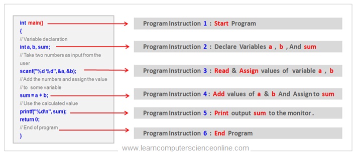
চিত্র ৫: Program statement থেকে machine instruction।
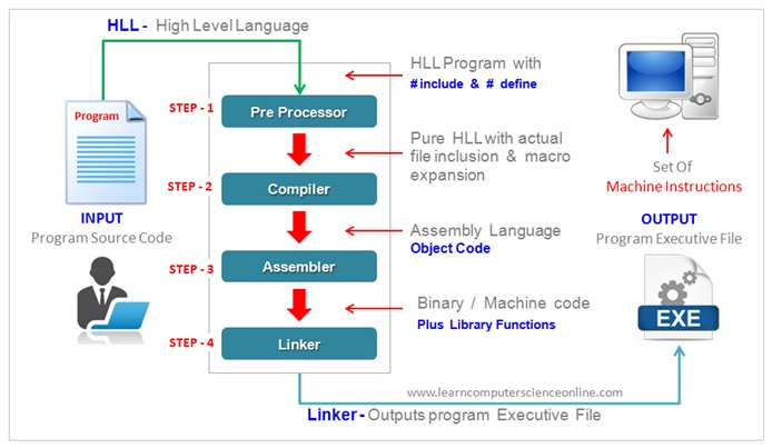
চিত্র ৬: Program compilation-এর সম্পূর্ণ flow।
একটি computer program অনেকগুলো program statement নিয়ে গঠিত। এগুলোকে Program Instruction-ও বলা হয়। প্রতিটি instruction একটি নির্দিষ্ট কাজ করে।
Program instruction-কে binary machine instruction-এ রূপান্তর করা হয়, যাতে CPU সরাসরি তা execute করতে পারে। Program execution শুরু করার জন্য Operating System এই machine instructionগুলো main memory বা RAM-এ load করে।
CPU instructionগুলো একটি একটি করে fetch করে। এরপর Control Unit instruction format অনুযায়ী প্রতিটি machine instruction decode করে।
Program-এর logic ও algorithm অনুযায়ী বিভিন্ন ধরনের instruction ব্যবহার করা হয়। যেমন:
- Input operation
- Output operation
- Arithmetic calculation
- Logical decision-making operation
Compilation-এর সময় প্রতিটি program instruction binary machine instruction-এ রূপান্তরিত হয়।
Programming language-এর ধরন অনুযায়ী compiler পুরো program-কে executable code-এ রূপান্তর করতে পারে। এই executable code অনেকগুলো machine instruction নিয়ে গঠিত। Interpreted language-এর ক্ষেত্রে conversion line by line হয়।
Executable code-এ binary machine instruction থাকে, যা CPU সরাসরি decode ও execute করতে পারে।
৫. Central Processing Unit (CPU) কী?
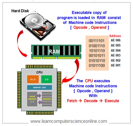
চিত্র ৭: CPU কীভাবে program execute করে।
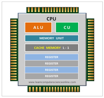
চিত্র ৮: CPU-এর প্রধান internal unit।
Central Processing Unit (CPU) হলো computer system-এর brain বা প্রধান processing unit। এটি system-কে আসল processing power দেয়।
CPU-এর প্রধান কাজ হলো:
- Computer program execute করা
- Computer system-এর সব operation নিয়ন্ত্রণ করা
CPU-এর ভেতরে কয়েকটি unit থাকে এবং প্রতিটি unit নির্দিষ্ট কাজ করে। গুরুত্বপূর্ণ unitগুলো হলো:
- Memory Unit (MU)
- Arithmetic Logic Unit (ALU)
- Control Unit (CU)
CPU বারবার Machine Cycle চালিয়ে program instruction execute করে।
৬. CPU Instruction Set Architecture (ISA)
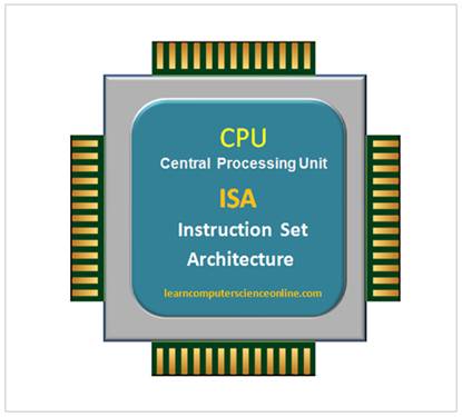
চিত্র ৯: ISA-এর basic position এবং কাজ।
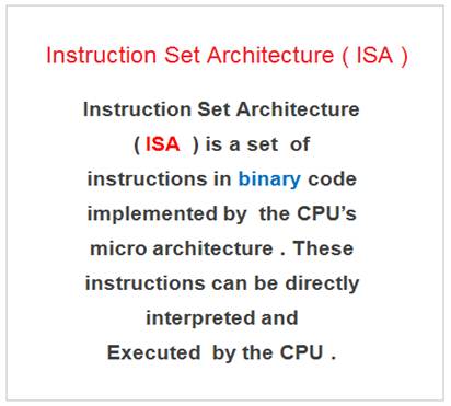
চিত্র ১০: Microprocessor-এর ISA ও instruction support।
প্রতিটি microprocessor chip কিছু নির্দিষ্ট binary command support করে, যেগুলো CPU decode ও execute করতে পারে।
Processor chip তৈরির সময় এই command set microprocessor-এর circuit-এর মধ্যে hardwired বা স্থায়ীভাবে যুক্ত করা হয়। CPU যে command set support করে, তাকে Instruction Set Architecture (ISA) বলা হয়।
বিভিন্ন processor-এর ISA আলাদা হতে পারে। তাই compiler একটি নির্দিষ্ট platform-এর জন্য program compile করে। Compiler এমন executable code তৈরি করে, যা সেই platform-এ execute করা যায়।
৭. Instruction Format কী?
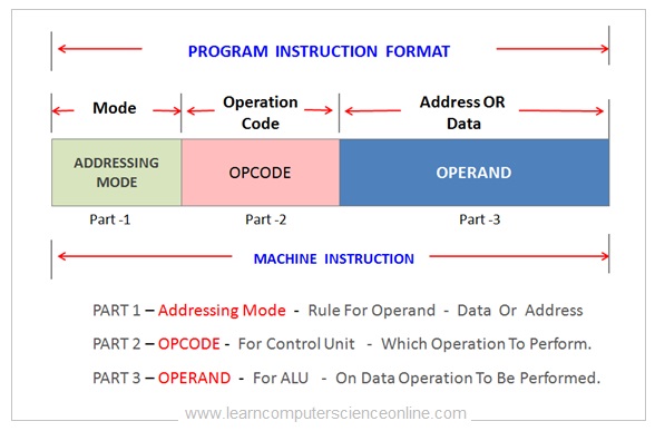
চিত্র ১১: Addressing Mode, Opcode ও Operand field।
একটি computer program-এ অনেক instruction থাকে, যা CPU-কে নির্দিষ্ট operation করতে নির্দেশ দেয়।
একটি instruction execute করার জন্য CPU-কে জানতে হয়:
- কোন operation করতে হবে
- কোন data-এর ওপর operation করতে হবে
- সেই data কোথায় আছে
এই তথ্যগুলো Instruction Format থেকে পাওয়া যায়।
CPU main memory বা RAM থেকে instruction একটি একটি করে fetch করে। এরপর CPU-এর Control Unit instruction decode করে।
Control Unit instruction format অনুযায়ী instruction decode করে। Instruction format থেকে জানা যায়:
- কোন operation করতে হবে (Opcode)
- Operand-এর effective address
- যে data-এর ওপর কাজ হবে (Operand)
Instruction Format একটি program instruction-এর layout ও structure নির্ধারণ করে। এর ফলে CPU instruction decode করে প্রয়োজনীয় operation করতে পারে।
Instruction Format প্রধানত তিনটি অংশ নিয়ে গঠিত:
- Addressing Mode
- Opcode
- Operand
Machine Instruction Format
| Part | Simple meaning in Bangla |
|---|---|
| Addressing Mode | Operand বা data কীভাবে পাওয়া যাবে |
| Opcode | CPU কোন operation করবে |
| Operand | যে data-এর ওপর operation হবে অথবা তার reference |
৮. Opcode কী?
Microprocessor architecture-এ Opcode হলো machine instruction-এর সেই অংশ, যা CPU-কে কোন operation করতে হবে তা জানায়।
Processor-এর ISA অনুযায়ী Opcode Control Unit-কে data বা operand-এর ওপর নির্দিষ্ট operation করতে নির্দেশ দেয়।
৯. Operand কী?
Microprocessor architecture-এ Operand হলো সেই data, যার ওপর CPU প্রয়োজনীয় operation করে।
Machine instruction-এর Operand field-এ থাকতে পারে:
- সরাসরি actual data, অথবা
- Data-এর reference, যেমন actual data রাখা আছে এমন memory address
CPU Addressing Mode অনুযায়ী Operand field-এর অর্থ বোঝে। বিভিন্ন instruction format-এ বিভিন্ন ধরনের Addressing Mode ব্যবহার করা হতে পারে।
১০. Addressing Mode কী?
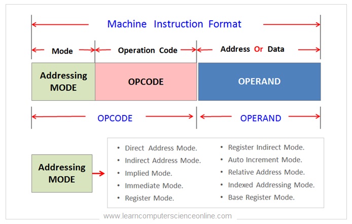
চিত্র ১২: Addressing Mode কীভাবে operand locate করে।
Microprocessor architecture-এ Addressing Mode হলো machine instruction-এর সেই অংশ, যা CPU-কে Operand কীভাবে বুঝতে বা access করতে হবে তা জানায়।
এটি বলে দেয় Operand-এর মধ্যে সরাসরি data আছে, নাকি data-এর indirect reference আছে।
Operand bits দিয়ে বোঝানো হতে পারে:
- সরাসরি একটি value
- Main memory-এর একটি address
- CPU register-এর number
Operand field-এ কোন ধরনের value আছে, তা Addressing Mode চিহ্নিত করে।
Indirect Addressing ব্যবহার করা হলে Operand-এ এমন একটি memory address থাকে, যা actual data-এর location নির্দেশ করে।
Instruction-এর ধরন অনুযায়ী machine-code instruction format-এ দশ ধরনের Addressing Mode ব্যবহার করা যেতে পারে।
১১. Machine Cycle কী?
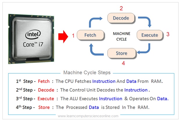
চিত্র ১৩: Machine Cycle-এর প্রধান operation।
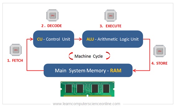
চিত্র ১৪: Instruction Cycle, Machine Cycle এবং clock state-এর সম্পর্ক।
Operating System executable program code এবং যে data process করতে হবে তা main memory বা RAM-এ load করে। তখন main memory-তে program-এর machine instruction থাকে।
এই machine instructionগুলো execute করার দায়িত্ব CPU-এর। যেকোনো কাজ করার জন্য CPU বারবার কিছু নির্দিষ্ট ধাপ অনুসরণ করে। এই ধাপগুলোর ধারাকে Machine Cycle বলা হয়।
Machine Cycle হলো Instruction Cycle-এর একটি অংশ। একটি instruction execute করতে CPU-কে কয়েকটি Machine Cycle চালাতে হতে পারে।
Machine Cycle হলো microprocessor-এর কোনো কাজ সম্পন্ন করার মৌলিক operation। Instruction Cycle-এর প্রতিটি অংশ সম্পন্ন করতে নির্দিষ্ট সংখ্যক Machine Cycle লাগতে পারে।
Program instruction একটি একটি করে execute করার জন্য CPU একের পর এক Machine Cycle চালায়।
Instruction Cycle-এর চারটি operation হলো:
- Fetch
- Decode
- Execute
- Store
Fetch, Decode, Execute এবং Store operation সম্পন্ন করতে CPU কয়েক round Machine Cycle চালায়।
তাই একটি program instruction execute করতে এক বা একাধিক Machine Cycle লাগতে পারে। কতগুলো লাগবে তা instruction-এর ধরন ও CPU architecture-এর ওপর নির্ভর করে।
উদাহরণ হিসেবে, একই instruction execute করতে 8085 ও 8086 processor-এর ভিন্ন সংখ্যক Machine Cycle লাগতে পারে।
১২. Instruction Cycle ও Clock Pulse
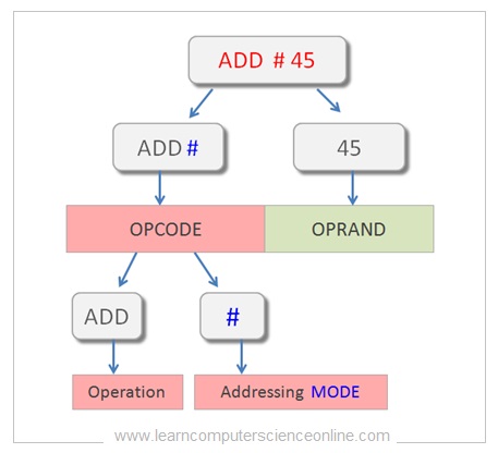
চিত্র ১৫: Instruction format সহ Instruction Cycle।
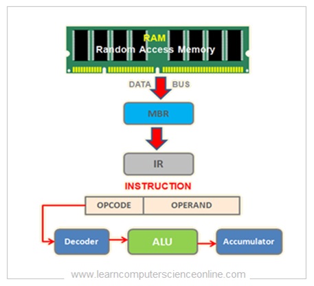
চিত্র ১৬: Fetch, Decode ও Execute-এর instruction flow।
সহজভাবে, CPU একটি machine instruction fetch ও execute করতে যে সময় নেয়, তাকে Instruction Cycle বলা হয়।
Computer program-এ বিভিন্ন ধরনের instruction থাকে। Instruction-এর জটিলতা অনুযায়ী CPU-এর একটি instruction execute করতে এক বা একাধিক Machine Cycle লাগতে পারে।
তাই Machine Cycle হলো Instruction Cycle-এর অংশ। তবে computing-এর আলোচনায় CPU-এর instruction execution mechanism বোঝাতে কখনও কখনও Machine Cycle ও Instruction Cycle—দুই শব্দই ব্যবহার করা হয়।
Processor একটি internal clock দ্বারা পরিচালিত হয়। এই clock নিয়মিত clock pulse তৈরি করে। Analog clock signal-কে digital square-wave clock pulse-এ রূপান্তর করা হয়।
CPU-কে চালানো clock-এর frequency-কে Processor Frequency বলা হয়। সাধারণভাবে frequency বেশি হলে instruction দ্রুত process করা যায়।
প্রতিটি clock cycle-এ CPU instruction execution-এর একটি অংশ সম্পন্ন করে। এই অংশটি Fetch, Decode, Execute অথবা Store operation হতে পারে।
প্রতিটি program instruction বিভিন্ন execution phase-এর মধ্য দিয়ে যায়। সাধারণভাবে CPU চারটি clock cycle-এ একটি Instruction Cycle সম্পন্ন করে।
তবে নিচের বিষয়গুলোর কারণে কিছু instruction execute করতে বেশি clock tick লাগতে পারে:
- Instruction-এর জটিলতা
- Instruction-এর ধরন
- Addressing Mode
১৩. CPU Clock Speed ও Instruction Cycle
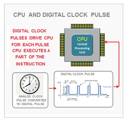
চিত্র ১৭: CPU clock pulse ও timing signal।
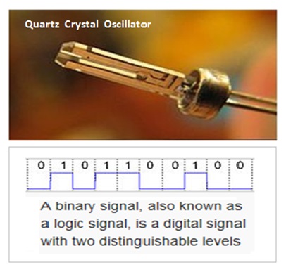
চিত্র ১৮: Control Unit-এর timing and control logic।
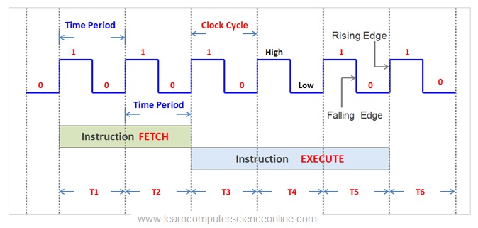
চিত্র ১৯: Clock cycle-এর সঙ্গে instruction step-এর সম্পর্ক।
CPU-এর internal clock নিয়মিত clock pulse তৈরি করে। প্রতিটি clock pulse-এ CPU instruction execution-এর একটি অংশ করে।
তাই সাধারণভাবে clock speed বেশি হলে CPU দ্রুত execute করতে পারে। Clock speed Hertz (Hz)-এ মাপা হয়। আধুনিক CPU-এর speed সাধারণত Gigahertz (GHz)-এ প্রকাশ করা হয়।
Oscillator-এর দুটি pulse-এর মাঝের সময়কে Clock Cycle বলা হয়।
এক সেকেন্ডে বেশি clock pulse হলে processor দ্রুত কাজ করতে পারে। Clock speed-এর সাধারণ unit হলো:
- Megahertz বা MHz
- Gigahertz বা GHz
উদাহরণ হিসেবে, 3 GHz clock-speed-এর একটি processor প্রতি সেকেন্ডে:
টি clock cycle সম্পন্ন করে।
Processor-এর speed আরও কিছু বিষয়ের ওপরও অনেকটা নির্ভর করে:
- Processor-এর ধরন
- Processor-এর Microarchitecture
- একটি instruction সম্পন্ন করতে প্রয়োজনীয় Clock Cycle-এর সংখ্যা
১৪. Pipelined Architecture
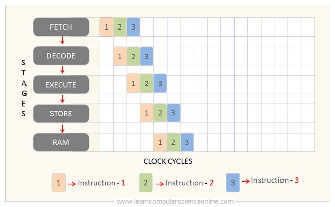
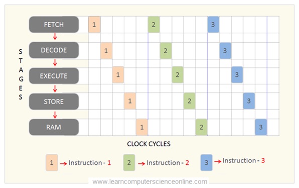
চিত্র ২০: Overlap করে Pipeline Instruction Execution।
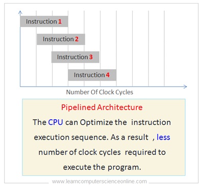
চিত্র ২১: CPU Pipelined Architecture।
Instruction Pipelining কী?
Processor-এর speed বাড়ানোর জন্য hardware industry নিয়মিত নতুন technology তৈরি করছে। Computer development শুরু হওয়ার পর থেকে processor-এর performance অনেক উন্নত হয়েছে।
Pipelined Architecture বা Instruction Pipelining CPU-এর performance অনেক বাড়িয়েছে। একই সংখ্যক Clock Cycle ব্যবহার করে CPU বেশি instruction process করতে পারে।
CPU architecture অনুযায়ী instruction processing দুইভাবে হতে পারে:
- Pipelined Processing
- Non-Pipelined Processing
Instruction Pipelining-এর ধারণাকে factory-এর Assembly Line-এর সঙ্গে তুলনা করা যায়।
Assembly Line-এ production process-কে কয়েকটি কাজ বা stage-এ ভাগ করা হয়। ফলে একই সময়ে আলাদা আলাদা কাজ করা যায় এবং production rate বাড়ে।
একইভাবে, Pipelined Architecture-এ instruction execution-কে কয়েকটি নির্দিষ্ট stage-এ ভাগ করা হয়। যেমন:
- Fetch
- Decode
- Execute
প্রতিটি Clock Cycle-এ CPU একটি instruction-এর একটি stage সম্পন্ন করে।
Pipeline Processing-এর মাধ্যমে CPU একই সময়ে কয়েকটি instruction-এর আলাদা অংশ process করতে পারে। ফলে program instructionগুলো তুলনামূলক কম Clock Cycle-এ সম্পন্ন করা যায়।
CPU parallelভাবে বেশি instruction process করতে পারে। অন্যদিকে Non-Pipelined CPU এক সময়ে শুধু একটি instruction execute করে। অধিকাংশ আধুনিক processor Instruction Pipelining support করে।
Instruction Pipelining-এ প্রতিটি Clock Cycle-এ CPU instruction-এর একটি অংশ সম্পন্ন করে। এটি Fetch, Decode অথবা Execute operation হতে পারে।
মূল লেখার উদাহরণ অনুযায়ী, একটি Machine Cycle round সম্পন্ন করতে বারোটি Clock Cycle লাগে। আর instruction-এর জটিলতা অনুযায়ী একটি Instruction Cycle-এর জন্য এক থেকে চারটি Machine Cycle লাগতে পারে।
Pipelined Architecture কী?
Pipelined Architecture-এ CPU একই সময়ে একাধিক instruction-এর বিভিন্ন অংশ process করতে পারে।
ফলে CPU instruction execution sequence আরও ভালোভাবে ব্যবহার করতে পারে। একই সংখ্যক instruction execute করতে তুলনামূলক কম Clock Cycle লাগে।
১৫. Non-Pipelined Architecture
চিত্র ২২: একটির পর একটি Non-Pipeline Instruction Execution।
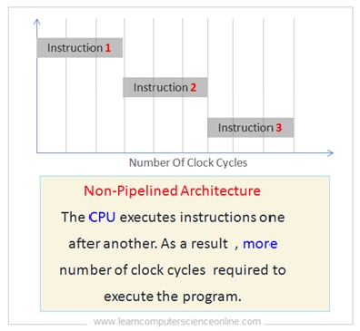
চিত্র ২৩: CPU Non-Pipelined Architecture।
Non-Pipelined Architecture-এ CPU program instruction একটির পর একটি execute করে। এটি একই সময়ে কয়েকটি instruction parallelভাবে process করতে পারে না।
ফলে Pipelined CPU-এর মতো instruction execution sequence ভালোভাবে ব্যবহার করা সম্ভব হয় না।
তাই একই সংখ্যক instruction execute করতে Pipelined Architecture-এর তুলনায় Non-Pipelined Architecture-এ বেশি Clock Cycle লাগে।
১৬. Fetch–Decode–Execute Cycle: ধাপে ধাপে
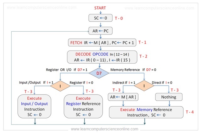
চিত্র ২৪: Fetch–Decode–Execute-এর সম্পূর্ণ CPU flow।
CPU যে প্রতিটি instruction execute করে, তা বিভিন্ন Clock Cycle-এ বিভিন্ন phase-এর মধ্য দিয়ে যায়।
Instruction Cycle-এর ধাপগুলো ভালোভাবে বোঝার জন্য CPU-এর শুরু করা operationগুলো ধারাবাহিকভাবে দেখা যায়।
ধাপ ১: Instruction Cycle শুরু
Instruction Cycle-এর প্রথম phase হলো Fetch Phase। শুরুতে Sequence Counter বা SC-এর মান zero করা হয়।
ধাপ ২: Clock Pulse \(T_0\)-তে Fetch Phase
Program Counter বা PC register-এ পরবর্তী instruction-এর address থাকে।
প্রথম Clock Cycle \(T_0\)-তে PC-তে থাকা address Address Register বা AR-এ পাঠানো হয়।
ধাপ ৩: Clock Pulse \(T_1\)-তে Fetch Phase
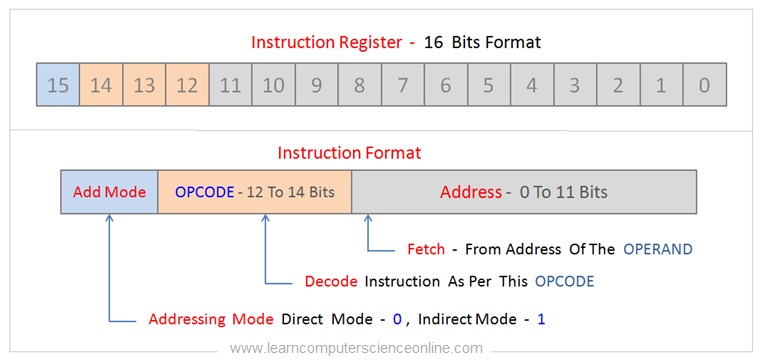
চিত্র ২৫: \(I\) bit, Opcode এবং Address field-সহ 16-bit instruction।
পরের Clock Cycle \(T_1\)-তে memory থেকে instruction fetch করে Instruction Register বা IR-এ রাখা হয়।
একই সময়ে Program Counter বা PC-এর মান এক বাড়ানো হয়।
এখন PC পরবর্তী যে instruction fetch করা হবে, তার memory location নির্দেশ করে।
Instruction Register বা IR একটি 16-bit register এবং এটি 16-bit instruction format support করে।
| Bit position | Field | সহজ বাংলা |
|---|---|---|
| Bit 15 | Addressing Mode or \(I\) bit | Direct না Indirect mode তা জানায় |
| Bits 12–14 | Opcode | কোন operation হবে তা জানায় |
| Bits 0–11 | Operand Address | Operand-এর address দেয় |
ধাপ ৪: Clock Pulse \(T_2\)-তে Decode Phase
Instruction Cycle-এর দ্বিতীয় প্রধান phase হলো Decode Phase।
Instruction fetch করে Instruction Register বা IR-এ রাখার পর CPU-এর Control Unit সেটি decode করে।
Bits 12, 13 ও 14-এ থাকা Opcode অনুযায়ী Control Unit instruction decode করে।
ধাপ ৫: Clock Pulse \(T_2\)-তে Instruction Type Decode করা
Control Unit প্রথমে instruction-এর ধরন নির্ধারণ করে। তিন ধরনের instruction হতে পারে:
- Memory-Reference Instruction
- Register-Reference Instruction
- Input/Output Instruction
Instruction-এর ধরন 3-to-8 Decoder দিয়ে decode করা হয়। \(D_7\)-এর value ব্যবহার করে instruction-এর ধরন নির্ধারণ করা হয়।
Three-bit Opcode দিয়ে আটটি value দেখানো যায়:
অর্থাৎ binary Opcode-এর range:
থেকে
ধাপ ৬: Clock Pulse \(T_3\)-তে Addressing Mode Decode করা
\(D_7 = 0\) হলে instruction-এর ধরন Memory-Reference Instruction।
\(D_7 = 1\) হলে instruction হতে পারে:
- Register-Reference Instruction, অথবা
- Input/Output Instruction
এরপর \(I\) bit পরীক্ষা করা হয়:
- \(D_7 = 1\) এবং \(I = 0\) হলে এটি Register-Reference Instruction।
- \(D_7 = 1\) এবং \(I = 1\) হলে এটি Input/Output Instruction।
Bit 15-এ থাকা \(I\) bit-এর value অনুযায়ী instruction-এর ধরন ও প্রয়োজনীয় decision নেওয়ার পর Decode Phase শেষ হয়।
Memory-Reference Instruction-এর ক্ষেত্রে Decode operation Addressing Mode-ও নির্ধারণ করে।
Bit 15-এ থাকা \(I\) bit-এর value অনুযায়ী Addressing Mode নির্ধারিত হয়:
- \(I = 0\) হলে Direct Addressing
- \(I = 1\) হলে Indirect Addressing
এরপর Decode Phase শেষ হয় এবং Execution Phase শুরু হয়।
ধাপ ৭: Clock Pulse \(T_4\)-তে Execution Phase
Decode Phase শেষ হলে Execution Phase শুরু হয়। এই phase-এ processor Accumulator Register-এ থাকা data বা Operand-এর ওপর প্রয়োজনীয় operation করে।
Register-Reference Instruction
Register-Reference Instruction-এর execution সরাসরি হয়। Processor প্রয়োজনীয় operation করে এবং Sequence Counter বা SC আবার zero করা হয়।
Input/Output Instruction
Input/Output Instruction-এর ক্ষেত্রে processor প্রয়োজনীয় I/O operation করে এবং Sequence Counter আবার zero করা হয়।
Memory-Reference Instruction
Memory-Reference Instruction-এর ক্ষেত্রে bit 15 থেকে বোঝা যায় Direct না Indirect Addressing ব্যবহার হবে।
Direct Memory Reference: \(I = 0\)
Direct Addressing-এ processor bits 0–11 দিয়ে দেখানো address থেকে data fetch করে তার ওপর প্রয়োজনীয় operation চালায়। এরপর Sequence Counter zero করা হয়।
Indirect Memory Reference: \(I = 1\)
Indirect Addressing-এ processor প্রথমে Effective Address বের করে। এরপর সেই Effective Address থেকে data fetch করে প্রয়োজনীয় operation চালায়। Bits 0–11 Effective Address-এর দিকে নির্দেশ করে। সবশেষে Sequence Counter zero করা হয়।
১৭. Halt Phase ও Interrupt
Execution Phase সম্পন্ন হলে control আবার Fetch Phase-এ ফিরে যায় এবং নতুন Instruction Cycle শুরু হয়।
Execution-এর পরে interrupt-এর কারণে halt signal এলে Instruction Cycle Halt Phase-এ যেতে পারে।
Processor interrupt handle করার পর আবার Instruction Cycle execution শুরু করে।
এক নজরে সম্পূর্ণ Flow
Program written in a high-level language
                    ↓
Compilation or interpretation
                    ↓
Binary machine instructions
                    ↓
Operating System loads instructions into RAM
                    ↓
PC points to the next instruction
                    ↓
Fetch → Decode → Execute → Store
                    ↓
SC returns to 0 and the next cycle begins
                    ↓
If an interrupt occurs: Halt/Handle Interrupt → Resume
সহজ বাংলায়:
High-level language-এ Program লেখা
                    ↓
Compile অথবা Interpret করা
                    ↓
Binary Machine Instruction তৈরি
                    ↓
Operating System instructionগুলো RAM-এ load করে
                    ↓
PC পরবর্তী instruction-এর address ধরে রাখে
                    ↓
Fetch → Decode → Execute → Store
                    ↓
SC আবার 0 হয় এবং পরবর্তী cycle শুরু হয়
                    ↓
Interrupt এলে: Halt/Interrupt Handle → আবার Resume
কী পরিষ্কার করা হয়েছে
Supplied Markdown থেকে নিচের non-lesson বিষয়গুলো বাদ দেওয়া হয়েছে:
- Udemy ও online course-এর advertisement
- “Join the Best Seller” promotional section
- Course promotion-এর description
- Advertisement image ও referral link
- “Read More” ও “Scroll back to top” navigation link
- খালি বা বারবার আসা “Instruction Cycle” heading
Original article-এর ২৫টি educational image-এর সবগুলোই বাংলা ও English—দুই অংশে রাখা হয়েছে। কোনো educational image recreate, replace বা skip করা হয়নি। শুধু article-এর ৬টি course/advertisement image বাদ দেওয়া হয়েছে।
সব definition, explanation, example, numerical fact, instruction field, register-transfer statement, clock timing, execution decision এবং interrupt-সম্পর্কিত শিক্ষামূলক content রাখা হয়েছে।
Instruction Cycle: Complete English Version
Computer Organization and Architecture
Note: This section contains the complete English version. All educational points, steps, examples, equations, register-transfer statements, timing details, and necessary diagrams have been retained. Advertisements, promotional material, unrelated links, and unnecessary duplicate images remain excluded.
Table of Contents
- What Is an Instruction Cycle?
- How Does a Computer Execute a Program?
- What Is a Computer Program?
- What Is a Program Instruction?
- What Is the Central Processing Unit?
- CPU Instruction Set Architecture (ISA)
- What Is an Instruction Format?
- What Is an Opcode?
- What Is an Operand?
- What Is an Addressing Mode?
- What Is a Machine Cycle?
- Instruction Cycle and Clock Pulses
- CPU Clock Speed and Instruction Cycle
- Pipelined Architecture
- Non-Pipelined Architecture
- Fetch–Decode–Execute Cycle: Step by Step
- Halt Phase and Interrupt
The instruction cycle is the time required by the CPU to execute one single instruction. It is a basic operation of the CPU and is commonly explained through three main steps: Fetch, Decode, and Execute.
The CPU repeatedly performs the Fetch–Decode–Execute Cycle to execute the instructions of a program. A machine cycle is a part of the instruction cycle.
The main function of a computer system is to execute programs. A computer program consists of a set of instructions. The Central Processing Unit (CPU) is responsible for executing these program instructions.
1. What Is an Instruction Cycle?
Figure 1: Overall flow of the CPU Instruction Cycle.
The program instructions are stored in the main memory or RAM. Computer memory is organized into many cells, and every cell or location has a specific memory address.
The processor starts program execution by fetching the machine instructions one by one from the main memory.
The CPU executes the instructions by repeatedly performing four operations:
- Fetch
- Decode
- Execute
- Store
Each part of the instruction cycle may require a number of machine cycles to complete.
Important clarification: The source first describes the cycle with three broad stages—Fetch, Decode, and Execute—and later describes Store as a fourth operation. Both descriptions refer to the same instruction-execution process; in the three-stage description, storing the result is treated as part of execution.
2. How Does a Computer Execute a Program?
Figure 2: Relationship between program execution and the Instruction Cycle.
To understand how a computer executes a program, we need to understand several related ideas:
- Computer program
- Program instruction
- Central Processing Unit or CPU
- Instruction Set Architecture or ISA
- Instruction format
- Opcode and operand
- Addressing mode
- Machine cycle
- CPU clock speed
- Instruction cycle
These basic ideas explain how the Control Unit decodes an instruction and how the CPU completes the instruction cycle.
3. What Is a Computer Program?
Figure 3: Basic concept of a Computer Program.
A computer system needs a set of instructions that directs it to perform the desired operations. A set of instructions that a computer can interpret and execute is called a computer program.
A computer program is an essential part of every computer system. The programming language is selected according to the type of software being developed.
Application software is generally written using high-level programming languages. Common examples include:
- C
- C++
- Java
- JavaScript
- Python
Program Compilation
Figure 4: Conversion of a high-level program into machine-readable code.
A program written in a high-level programming language must be converted into a machine-readable binary format.
Machine-code instructions are low-level binary instructions that can be executed directly by the computer.
4. What Is a Program Instruction?
Figure 5: Conversion of program statements into machine instructions.
Figure 6: Complete program-compilation flow.
A computer program consists of a set of program statements, also called program instructions. Each instruction performs a specific task.
Program instructions are converted into binary machine instructions that the CPU can directly execute. The operating system loads these machine instructions into the main memory or RAM to start program execution.
The CPU fetches the instructions one by one. The Control Unit decodes each machine instruction according to its instruction format.
A program uses different types of instructions according to its logic and algorithm. For example, an instruction may perform:
- Input operation
- Output operation
- Arithmetic calculation
- Logical decision-making operation
During compilation, every program instruction is converted into a binary machine instruction.
Depending on the programming language, a compiler may convert the complete program into executable code, which is a set of machine instructions. In an interpreted language, the conversion takes place line by line.
The executable code contains binary machine instructions that the CPU can directly decode and execute.
5. What Is the Central Processing Unit?
Figure 7: How the CPU executes a program.
Figure 8: Major internal units of the CPU.
The Central Processing Unit (CPU) is the brain and processing engine of a computer system. It provides the actual processing power of the system.
The main functions of the CPU are:
- Executing computer programs
- Controlling all operations performed by the computer system
The CPU internally consists of several units. Each unit performs a specific task. Important internal units include:
- Memory Unit (MU)
- Arithmetic Logic Unit (ALU)
- Control Unit (CU)
The CPU executes program instructions by repeatedly performing the machine cycle.
6. CPU Instruction Set Architecture (ISA)
Figure 9: Basic position and function of the ISA.
Figure 10: The microprocessor ISA and supported instructions.
Every microprocessor chip implements and supports a set of binary commands that it can decode and execute.
During processor-chip manufacturing, this set of commands is built or hardwired into the microprocessor circuitry. The command set implemented by a CPU is called its Instruction Set Architecture (ISA).
Because different processors may use different ISAs, a compiler compiles a program for a specific platform. It generates executable code that can run on that platform.
7. What Is an Instruction Format?
Figure 11: Addressing Mode, Opcode, and Operand fields.
A computer program contains many instructions that direct the CPU to perform specific operations.
To execute an instruction, the CPU needs to know:
- Which operation must be performed
- On which data the operation must be performed
- Where that data is located
This information is provided by the instruction format.
The CPU fetches instructions one by one from the main memory or RAM. Its Control Unit then decodes each instruction.
The Control Unit decodes an instruction according to its format. The format provides:
- The operation to perform (Opcode)
- The effective address of the operand
- The data on which the operation will be performed (Operand)
The instruction format defines the layout and structure of a program instruction so the CPU can decode it and perform the desired operation.
An instruction format mainly contains three parts:
- Addressing Mode
- Opcode
- Operand
Machine Instruction Format
| Part | Simple meaning |
|---|---|
| Addressing Mode | How the operand or data will be obtained |
| Opcode | Which operation the CPU will perform |
| Operand | The data on which the operation will be performed, or its reference |
8. What Is an Opcode?
In microprocessor architecture, the Opcode is the part of a machine instruction that specifies which operation the CPU must perform.
The Opcode directs the CPU's Control Unit to perform an operation on the data or operand according to the processor's ISA.
9. What Is an Operand?
In microprocessor architecture, an Operand is the data on which the CPU performs the desired operation.
The Operand field of a machine instruction may specify:
- The actual data itself, or
- A reference to the data, such as a memory address containing the actual data
The CPU interprets the Operand field according to the addressing mode. Different instruction formats may use different addressing modes.
10. What Is an Addressing Mode?
Figure 12: How the Addressing Mode locates an operand.
In microprocessor architecture, the Addressing Mode is the part of a machine instruction that tells the CPU how to interpret or access the Operand.
It specifies whether the Operand contains direct data or an indirect reference to the data.
The Operand bits may represent:
- A direct value
- A main-memory address
- A CPU register number
The Addressing Mode identifies which type of value is present in the Operand field.
If indirect addressing is selected, the Operand contains a memory address that points to the actual data.
Machine-code instruction formats can use ten different types of addressing modes, depending on the type of instruction.
11. What Is a Machine Cycle?
Figure 13: Major operations of a Machine Cycle.
Figure 14: Relationship among an Instruction Cycle, Machine Cycles, and clock states.
The Operating System loads the executable program code and the data to be processed into the main memory or RAM. The main memory then contains the program's machine instructions.
The CPU is responsible for executing these machine instructions. To perform any task, it repeatedly follows a sequence of steps. This sequence is called a Machine Cycle.
A Machine Cycle is part of an Instruction Cycle. The CPU may perform several machine cycles to execute one instruction.
The Machine Cycle is the basic operation used by a microprocessor to perform an activity. A specific number of machine cycles may be required to complete each part of the Instruction Cycle.
The CPU continuously performs machine cycles to execute program instructions one by one.
The Instruction Cycle contains four operations:
- Fetch
- Decode
- Execute
- Store
The CPU performs a number of Machine Cycle rounds to complete these Fetch, Decode, Execute, and Store operations.
Therefore, one program instruction may need one or more Machine Cycles. The required number depends on the instruction type and CPU architecture.
For example, the 8085 and 8086 processors require different numbers of Machine Cycles to execute the same instruction.
12. Instruction Cycle and Clock Pulses
Figure 15: Instruction Cycle with the instruction format.
Figure 16: Instruction flow through Fetch, Decode, and Execute.
In simple words, the Instruction Cycle is the time taken by the CPU to fetch and execute one machine instruction.
A computer program contains different types of instructions. According to the complexity of an instruction, the CPU may need one or more Machine Cycles to execute it.
Therefore, a Machine Cycle is a part of an Instruction Cycle. However, in computing discussions, the terms Machine Cycle and Instruction Cycle are sometimes both used while explaining the CPU's instruction-execution mechanism.
The processor is driven by an internal clock. This clock produces a steady stream of clock pulses. The analog clock signal is converted into a digital square-wave clock pulse.
The frequency of the clock that drives the CPU is called the processor frequency. Generally, a higher frequency allows instructions to be processed faster.
During each clock cycle, the CPU completes a part of the instruction-execution process. That part may be a Fetch, Decode, Execute, or Store operation.
Every program instruction passes through different execution phases. The CPU commonly completes one Instruction Cycle in four clock cycles.
However, some instructions may take more clock ticks depending on:
- Instruction complexity
- Instruction type
- Addressing mode
13. CPU Clock Speed and Instruction Cycle
Figure 17: CPU clock pulses and timing signals.
Figure 18: Timing and control logic of the Control Unit.
Figure 19: Relationship between clock cycles and instruction steps.
The CPU's internal clock produces a steady stream of clock pulses. For each clock pulse, the CPU performs a part of instruction execution.
Therefore, a faster clock speed generally provides a faster CPU execution speed. Clock speed is measured in Hertz (Hz). Modern CPU speeds are commonly expressed in Gigahertz (GHz).
A clock cycle is the time between two pulses of an oscillator.
A processor can work faster when it receives more clock pulses per second. Common clock-speed units are:
- Megahertz or MHz
- Gigahertz or GHz
For example, a processor with a clock speed of 3 GHz performs:
clock cycles per second.
Processor speed also depends greatly on other factors, including:
- Processor type
- Processor microarchitecture
- Number of clock cycles required by an instruction
14. Pipelined Architecture
Figure 20: Overlapped Pipeline Instruction Execution.
Figure 21: CPU Pipelined Architecture.
What Is Instruction Pipelining?
The hardware industry continues to develop technologies for improving processor speed. Processor performance has improved significantly since the beginning of computer development.
Pipelined Architecture or Instruction Pipelining has significantly improved CPU performance. It allows the CPU to process more instructions within the same number of clock cycles.
Depending on CPU architecture, instruction processing can be described in two modes:
- Pipelined processing
- Non-pipelined processing
The idea of Instruction Pipelining can be compared to production on an assembly line.
On an assembly line, the production process is divided into several jobs so that different jobs can be performed at the same time. This method increases the production rate.
Similarly, in a pipelined architecture, instruction execution is divided into fixed stages, such as:
- Fetch
- Decode
- Execute
During each clock cycle, the CPU completes one stage of an instruction.
Pipeline processing allows the CPU to process parts of several instructions at the same time. Therefore, the program instructions can be completed using fewer clock cycles.
The CPU can process more instructions in parallel. By comparison, a non-pipelined CPU executes only one instruction at a time. Most modern processors support Instruction Pipelining.
In Instruction Pipelining, the CPU completes one part of an instruction during each clock cycle. It may be a Fetch, Decode, or Execute operation.
According to the source example, one round of a Machine Cycle needs twelve Clock Cycles, while one Instruction Cycle may need between one and four Machine Cycles depending on instruction complexity.
What Is Pipelined Architecture?
In a Pipelined Architecture, the CPU can process parts of multiple instructions simultaneously.
As a result, the CPU can optimize the instruction-execution sequence. Therefore, fewer Clock Cycles are required to execute the same number of instructions.
15. Non-Pipelined Architecture
Figure 22: Sequential Non-Pipeline Instruction Execution.
Figure 23: CPU Non-Pipelined Architecture.
In a Non-Pipelined Architecture, the CPU executes program instructions one after another. It cannot process several instructions in parallel.
As a result, the CPU cannot optimize the instruction-execution sequence in the same way as a pipelined CPU.
Therefore, a Non-Pipelined Architecture requires more Clock Cycles than a Pipelined Architecture to execute the same number of instructions.
16. Fetch–Decode–Execute Cycle: Step by Step
Figure 24: Complete CPU flow of Fetch, Decode, and Execute.
Every instruction executed by the CPU passes through different phases at different clock cycles.
To understand the step-by-step execution of an Instruction Cycle, we can divide the cycle into a series of operations initiated by the CPU.
Step 1: Instruction Cycle Starts
The first phase of the Instruction Cycle is the Fetch Phase. The cycle begins by initializing the Sequence Counter (SC) to zero.
Step 2: Fetch Phase at Clock Pulse \(T_0\)
The Program Counter (PC) register contains the address of the next instruction.
During the first clock cycle, \(T_0\), the address stored in the PC is transferred to the Address Register (AR).
Step 3: Fetch Phase at Clock Pulse \(T_1\)
Figure 25: A 16-bit instruction with the \(I\) bit, Opcode, and Address field.
During the next clock cycle, \(T_1\), the instruction is fetched from memory and loaded into the Instruction Register (IR).
At the same time, the Program Counter (PC) is incremented by one.
The PC now points to the memory location of the next instruction to be fetched.
The Instruction Register (IR) is a 16-bit register that supports a 16-bit instruction format.
The 16-bit instruction format contains three parts:
| Bit position | Field | Meaning |
|---|---|---|
| Bit 15 | Addressing Mode or \(I\) bit | Indicates Direct or Indirect mode |
| Bits 12–14 | Opcode | Indicates which operation will be performed |
| Bits 0–11 | Operand Address | Provides the address of the operand |
Step 4: Decode Phase at Clock Pulse \(T_2\)
The second major phase of the Instruction Cycle is the Decode Phase.
After the instruction is fetched into the Instruction Register (IR), the CPU's Control Unit decodes it.
The Control Unit decodes the instruction according to the Opcode represented by bits 12, 13, and 14.
Step 5: Decode the Instruction Type at Clock Pulse \(T_2\)
The Control Unit first determines the type of instruction. The three possible instruction types are:
- Memory-reference instruction
- Register-reference instruction
- Input/Output instruction
The instruction type is decoded by a 3-to-8 decoder. The type is determined with the help of the value of \(D_7\).
A three-bit Opcode can represent eight values:
The binary Opcode range is:
to
Step 6: Decode Addressing Mode at Clock Pulse \(T_3\)
If \(D_7 = 0\), the instruction is a Memory-Reference Instruction.
If \(D_7 = 1\), the instruction may be either:
- A Register-Reference Instruction, or
- An Input/Output Instruction
The \(I\) bit is then checked:
- If \(D_7 = 1\) and \(I = 0\), it is a Register-Reference Instruction.
- If \(D_7 = 1\) and \(I = 1\), it is an Input/Output Instruction.
The Decode Phase ends after the instruction type and the required decision based on the \(I\) bit at bit position 15 have been determined.
For a Memory-Reference Instruction, the Decode operation also determines the Addressing Mode.
The Addressing Mode depends on the \(I\) bit at bit position 15:
- If \(I = 0\), the mode is Direct.
- If \(I = 1\), the mode is Indirect.
After this, the Decode Phase ends and the Execution Phase begins.
Step 7: Execution Phase at Clock Pulse \(T_4\)
After the Decode Phase, the Execution Phase begins. During this phase, the processor performs the required operation on the data or Operand placed in the Accumulator Register.
Register-Reference Instruction
For a Register-Reference Instruction, execution is straightforward. The processor performs the required operation, and the Sequence Counter (SC) is reset to zero.
Input/Output Instruction
For an Input/Output Instruction, the processor performs the required I/O operation, and the Sequence Counter is reset to zero.
Memory-Reference Instruction
For a Memory-Reference Instruction, bit 15 determines whether execution uses Direct or Indirect Addressing.
Direct Memory Reference: \(I = 0\)
For Direct Addressing, the processor performs the required operation on the data fetched from the address represented by bits 0–11. Then the Sequence Counter is reset to zero.
Indirect Memory Reference: \(I = 1\)
For Indirect Addressing, the processor first finds the Effective Address. It then fetches the data from that Effective Address and performs the required operation. Bits 0–11 point toward the Effective Address. Finally, the Sequence Counter is reset to zero.
17. Halt Phase and Interrupt
After the Execution Phase is complete, control returns to the Fetch Phase and a new Instruction Cycle begins.
After execution, the Instruction Cycle may enter the Halt Phase if it receives a halt signal caused by an interrupt.
The processor handles the interrupt and then resumes Instruction Cycle execution.
Complete Flow at a Glance
Clean-up Record
The following non-lesson items from the supplied Markdown were removed:
- Udemy and online-course advertisements
- “Join the Best Seller” promotional section
- Promotional course descriptions
- Advertisement images and referral links
- “Read More” and “Scroll back to top” navigation links
- Empty or repeatedly inserted “Instruction Cycle” headings
All 25 educational images from the original article appear in both the Bangla and English sections. No educational image was recreated, replaced, or skipped. Only the article’s six course/advertisement images were removed.
All definitions, explanations, examples, numerical facts, instruction fields, register-transfer statements, clock timings, execution decisions, and interrupt-related lesson content have been retained.