Control Signal: Types and Role
Control signals coordinate the activities of CPU components such as the Arithmetic Logic Unit (ALU), registers, memory, and buses. These binary signals are generated by the Control Unit. They ensure that instruction fetching, decoding, execution, and data transfer take place in the correct sequence.
Control signals work as the internal communication system of the CPU. They direct how, when, and where each component should operate while an instruction is being executed.
- Control signals are binary commands generated by the Control Unit to manage CPU operations.
- They synchronize arithmetic operations, memory access, and instruction flow.
- Each instruction needs a particular set of control signals to move data and activate the correct components at the correct time.
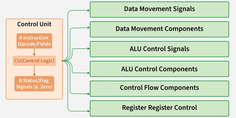
Types of Control Signals
Control signals are grouped according to the processor functions they control.
1. Data Movement Signals
These signals control data transfer between the CPU and memory, and between internal components such as registers and the ALU.
- Read: Transfers data from memory to the CPU.
- Write: Transfers data from the CPU to memory.
- Load: Loads data into a register from another component.
- Store: Saves data from a register into memory.
2. ALU Control Signals
These signals determine the operation of the Arithmetic Logic Unit.
- ALUOp: Specifies the operation that the ALU must perform, such as addition, subtraction, AND, or OR.
- Enable ALU: Activates the ALU so that it can perform the required computation.
3. Control Flow Signals
These signals guide the sequence of instructions, particularly when a program contains decisions or loops.
- Branch: Moves program execution to another instruction when a condition is true.
- Jump: Unconditionally redirects execution to a new instruction address.
- PC Write: Updates the Program Counter with the address of the next instruction.
4. Register Control Signals
These signals determine how registers are accessed or changed during instruction execution.
- Register Write: Enables data to be written into a register.
- Register Read: Enables data to be read from a register.
- Select Register: Selects the register or registers required for a particular operation.
Summary of Control-Signal Types
| Type | Signals | Function |
|---|---|---|
| Data Movement Signals | Read, Write, Load, Store | Control data transfer between the CPU, memory, registers, and other internal components. |
| ALU Control Signals | ALUOp, Enable ALU | Select an arithmetic or logical operation and activate the ALU. |
| Control Flow Signals | Branch, Jump, PC Write | Direct instruction sequencing and update the Program Counter. |
| Register Control Signals | Register Write, Register Read, Select Register | Control the selection, reading, and writing of registers. |
Role of Control Signals
Control signals have a central role in coordinating the CPU and its subsystems. They do more than turn components on or off. They maintain proper timing, establish data flow, and support decision-making inside the processor.
1. Instruction Execution
Every instruction, such as ADD, LOAD, or JUMP, is completed through a set of operations. Control signals:
- Activate the correct datapath components, including the ALU, registers, and memory.
- Manage timing so that the operations occur in the correct sequence.
- Direct the instruction through the Fetch → Decode → Execute stages.
2. Synchronization of Components
All CPU components must work in synchronization.
- The ALU must wait until operands have been loaded from the registers.
- A memory write must occur only after the data is available and the address is valid.
Control signals prevent a component from acting before the required conditions are ready.
3. Datapath Management
The datapath is the route through which data moves among CPU components.
- Control signals select the source and destination of data.
- They configure multiplexers, buses, and buffers to create the required path.
4. Control of Arithmetic and Logic Operations
Control signals tell the ALU:
- Which operation it must perform, such as addition, subtraction, or AND.
- When it should perform that operation after the inputs become ready.
- When the result should be sent to a register or memory.
5. Decision-Making and Program Flow
During conditional execution:
- Branch control signals select the next instruction according to the result of a comparison.
- Jump signals redirect instruction flow for loops, function calls, and other required operations.
6. Efficient Use of Resources
Control signals activate only the components that are required at a particular time. This helps to:
- Reduce power consumption.
- Prevent hardware conflicts.
- Improve performance by avoiding unnecessary delays.
Example: Instruction Execution and Control Signals
Consider the instruction:
It means that the values stored in registers R2 and R3 are added, and the result is stored in register R1.
The following control signals are involved:
- Register Read: Activates the read lines for
R2andR3. - ALU Operation: Selects addition as the ALU operation.
- Enable ALU: Allows the ALU to execute the addition.
- Register Write: Enables the ALU result to be written into
R1. - Select Register: Selects
R1as the destination register.
Each signal must be activated at the correct time for the instruction to execute correctly.
Importance of Control Signals
Control signals are essential for coordinating and managing CPU operations. They support accurate instruction execution, efficient data handling, and logical decision-making inside the processor.
- They maintain synchronization and the correct sequence of CPU operations.
- They manage data flow and support conditional execution, including branches and loops.
- They connect instruction logic with the corresponding hardware behavior.