Magnetism
4.2 Biot–Savart Law or Laplace’s Law
According to scientific observation, a magnetic field is produced around a current-carrying conductor. To calculate the magnetic field or magnetic induction at any point, Biot and Savart formulated a law, which Laplace later used to derive a mathematical expression. In 1820, Biot and Savart demonstrated this relationship through an experiment. Hence, this is known as the Biot–Savart Law or Biot–Savart–Laplace Law. Using this law, the magnetic field due to various current elements of a conductor can be determined.
Determination of Magnetic Field Due to a Current Element
Law: The magnetic field \(\vec{dB}\) at a point in space due to a small current element depends on:
(i) The strength of the electric current \(i\),
(ii) The length of the current element \(dl\),
(iii) The sine of the angle between the direction of the current element and the line joining the element to the point of observation,
(iv) The inverse square of the distance between the current element and the observation point.
Explanation:
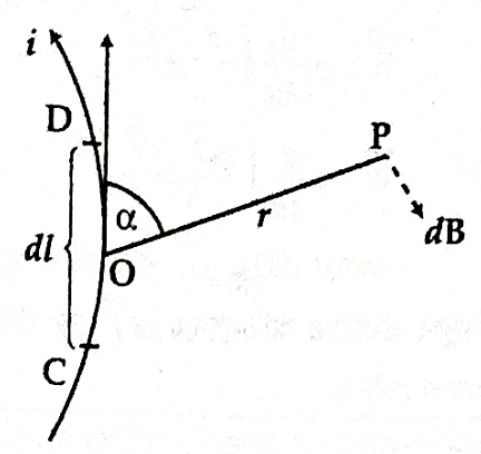
Let us consider a small part \(CD\) of a current-carrying conductor. The point \(P\) lies at a perpendicular distance \(r\) from a point \(O\) on the wire, and \(\angle COP = \alpha\). According to experimental results, the magnetic field \(dB\) at point \(P\) due to this element is:
(i) Proportional to the current \(i\):
\(dB \propto i\)
(ii) Proportional to the length of the element \(dl\):
\(dB \propto dl\)
(iii) Proportional to \(\sin \alpha\), where \(\alpha\) is the angle between the element and the position vector:
\(dB \propto \sin \alpha\)
(iv) Inversely proportional to the square of the distance \(r^2\):
\(dB \propto \frac{1}{r^2}\)
Therefore, combining all these dependencies:
Or,
Here, \(K\) is a proportionality constant whose value depends on the medium and the system of units. In SI units, for vacuum or air:
Thus, in vacuum or air, the Biot–Savart law becomes:
And in other media:
Or generally:
Here, \(\mu\) is the magnetic permeability of the medium.
To find the total magnetic field \(B\) at point \(P\) due to the entire conductor, we integrate all such small elements:
For vacuum or air:
For other media:
Now, expressing the vector form:
In vacuum:
In other media:
Here, \(dl\) is the infinitesimal length element in the direction of current. Hence, this quantity is called the current element \(i \cdot dl\).
Note:
Any magnetic field line due to a current element lies perpendicular to both the current direction and the position vector. Thus, only the perpendicular component contributes to \(dB\).
Key points:
-
If the angle between the element and the position vector is zero (i.e., they are aligned), then \(\alpha = 0^\circ\), and \(\sin \alpha = 0\). Therefore,
\(dB = 0\), no magnetic field is generated at that point. -
Maximum magnetic field is produced when the angle \(\alpha = 90^\circ\), so \(\sin \alpha = 1\). Therefore,
\(dB = \frac{\mu_0}{4\pi} \cdot \frac{i \cdot dl}{r^2}\), which is the maximum field value.
Hence, the magnetic field depends on the sine of the angle \(\alpha\) between the current element and the position vector.
Magnetic Force on a Current
Consider a wire of length \(l\) carrying a current \(i\) and placed in a magnetic field \(\vec{B}\):
![Diagram illustrating a current-carrying wire in a magnetic field]
The current \(i\) in the wire is carried by the free electrons, \(n\) being the number of free electrons per unit volume of the wire. The magnitude of the average force on one such electron is given by:
Since \(\theta = 90^\circ\), \(\sin \theta = 1\), we get:
Where:
- \(e\) is the charge of the electron,
- \(v_d\) is the drift velocity.
If \(l\) is the length of the wire, the total force on the free electrons in the wire is:
If the cross-sectional area of the wire is \(A\), then the total number of electrons in the wire is:
Therefore, the total force on the free electrons in the wire is:
But we know:
Where \(j\) is the current density, and:
Substituting into Equation (1):
So,
In vector form,
So, \(\vec{F} = i \vec{l} \times \vec{B}\) is the expression for the magnetic force on a current.
Lorentz Force
If a charged particle moves through a region in which both an electric field and a magnetic field are present, then the resultant force is given by:
This equation is known as the Lorentz Equation, and this force is called the Lorentz Force.
Thank you for the clarification. Here's the simplified and easy-to-follow version of your provided explanation, keeping it formal but not too bookish — like how a good Indian teacher might explain it in class with relatable terms:
Magnetic Force on a Current (Simplified Explanation)
What happens?
Let’s say you take a wire of length \(l\), and pass an electric current \(i\) through it. Now, place this wire inside a magnetic field \(\vec{B}\). What happens?
Even though the wire looks still from outside, inside it, millions of tiny free electrons are moving. These moving electrons feel a force because of the magnetic field.
Why do they feel force?
From physics, we know that whenever a charged particle (like an electron) moves in a magnetic field, it feels a force. That force is given by:
Here:
- \(q\) is the charge of one electron (in this case, \(e\))
- \(\vec{v}_d\) is the drift velocity — this is the average speed at which electrons move in the wire
- \(\vec{B}\) is the magnetic field
Now, if the magnetic field is perpendicular to the direction of motion (which is the usual case in such questions), the angle \(\theta = 90^\circ\), so:
What is the total force on all electrons?
If the wire has:
- Length = \(l\)
- Cross-sectional area = \(A\)
- Free electron density = \(n\) (i.e., how many free electrons in 1 m³ of wire)
Then, total number of free electrons = \(nAl\)
So, total magnetic force on all electrons = Number of electrons × Force on one
But what is \(v_d\) (drift velocity)?
We also know from current electricity:
Where \(j\) is current density. And:
Now plug this into our previous force formula:
Final Formula (Scalar and Vector Form)
- Scalar form: \(F = i l B\) (when \(i\), \(B\), and \(l\) are mutually perpendicular)
- Vector form: \(\vec{F} = i \vec{l} \times \vec{B}\)
So this is how we calculate the magnetic force on a current-carrying conductor.
Lorentz Force (Simplified Explanation)
What is it?
Suppose you have a charged particle (like an electron or proton), and it is moving in a region where:
- There is an electric field \(\vec{E}\)
- And also a magnetic field \(\vec{B}\)
Then the particle feels two forces at the same time:
- Electric force: \(q\vec{E}\)
- Magnetic force: \(q\vec{v} \times \vec{B}\)
So total force (called Lorentz force) is:
In short:
Lorentz force = Electric force + Magnetic force
This equation explains the complete effect on a moving charge in a combined electric and magnetic field.
Here is your translated and formatted version in bookish English, using Indian-friendly phrasing with simple words and proper structure suitable for textbooks:
Ampere’s Circuital Law (Ampere’s Law)**
Subject: Physics (Second Paper)
Page: 308
🔷 Statement of Ampere’s Law
Ampere’s Law can be stated as follows:
“The line integral of the magnetic field \(\vec{B}\) around any closed loop is equal to \(\mu_0\) times the total current \(i\) passing through the surface enclosed by that loop.”
This can be written mathematically as:
Where:
- \(\mu_0\) = Permeability of free space (a constant)
- \(d\vec{l}\) = Small displacement vector along the path
- \(\oint\) = Indicates a closed path (line integral around a loop)
🔶 Explanation in Simple Terms
Suppose current is flowing through a conducting wire. This electric current produces a magnetic field around the wire.
If we place a small magnetic needle (bar magnet) in this field, it gets rotated from its original position due to the magnetic force. That means a torque (twisting force) is acting on it.
The magnitude of this torque is given by:
Where:
- \(\vec{p}\) = Magnetic dipole moment of the bar magnet
- \(B\) = Strength of the magnetic field
- \(\theta\) = Angle between \(\vec{p}\) and \(\vec{B}\)
This tells us that:
🔸 Magnetic Field Around a Current-Carrying Wire
Now, let’s understand how the magnetic field behaves around a straight wire carrying current:
By conducting an experiment where we change:
- The current (i) through the wire, and
- The distance (r) from the wire where the magnetic field is measured,
we observe that:
Which means,
- Magnetic field increases with current,
- Magnetic field decreases with distance.
To make this a proper equation, we multiply with a constant:
Where:
- \(\mu_0 = 4\pi \times 10^{-7}\) Weber / Ampere-metre (Permeability of free space)
So, this becomes:
This is exactly Ampere’s Circuital Law again.
🌀 Visual Understanding
If we imagine a circular loop around the wire, all points on the circle are at equal distance \(r\) from the wire. The magnetic field \(B\) is the same at all points on the circle, and its direction is tangential to the circle (as shown in Figure 4.11(a)).
So, over the full circular path:
Again, we get:
✅ Summary Table
| Symbol | Meaning |
|---|---|
| \(\mu_0\) | Magnetic permeability of free space |
| \(\vec{B}\) | Magnetic field |
| \(\vec{l}\) | Small displacement along the path |
| \(i\) | Current flowing through enclosed surface |
| \(r\) | Distance from wire |
| \(\tau\) | Torque on magnetic dipole |
| \(\vec{p}\) | Magnetic moment of the bar magnet |
| \(\theta\) | Angle between \(\vec{p}\) and \(\vec{B}\) |